Criteria
Grip
We have done extensive research to find the best grip for our gripper. By using rubber pads our gripper has superior grip on the cup, therefore it is able to lift the cup without dropping it. Furthermore the frame of our gripper is designed so that it can exercise the highest possible force that the actuator can deliver.
Stability
By using an independent connection between the arm and the gripper our design has maximum stability, and therefor the spillage is reduced to a minimum. To increase the stability of the arm furthermore we added counterweight.
Materials
To reduce the weight of the gripper as much as possible we have considered multiple materials. The material that fitted our design the most was acrylic glass (Perspex). We chose Perspex because of its weight properties, its low costs and its ability to be produced easily.
Machining
The design of the components of our gripper required high accuracy. Because we wanted to use Perspex to manufacture the gripper, we were able to use a laser cutting machine. This insured minimal deviation. Other than that, we used metal nuts and bolts to attach parts of the gripper to one another.
Requirements
- The maximum weight of the cup is 0.5 kg.
- The weight has to be lifted 0.25 m.
- The weight has to be hold for at least 10 seconds in upward position.
- The actuators must be fitted so that they can be built in quickly.
Morphological analysis
Choosing our gripper
As each of us had come up with at least one design for both the gripper and the arm the gripper would be attached to, we now had eight designs to choose from. To reduce the number of options to just one design, we compared our ideas by creating morphological analyses. As a start, we compared our gripper-ideas based on the following criteria:
The stability of the gripper
A high score was given if the gripper was deemed to be stable during the lifting of the cup.
The weight of the gripper
The lower the weight of the gripper, the higher the given score.
The grip of the gripper on the cup
A high score was given if there was a high amount of friction between the cup and the gripper.
Outcome morphological analysis I
|
Gripper -> Criterion |
1 Stijn |
2 Naresh |
3 Esmée |
4 Daan |
5 Fernão |
6 Marko |
7 Marko2 |
8 Anna |
Weighing- factor |
|
Stability gripper |
7 |
8 |
7 |
7 |
8 |
8 |
7 |
8 |
9 |
|
Weight
gripper |
8 |
8 |
6 |
8 |
5 |
8 |
6 |
5 |
4 |
|
Grip
on cup |
9 |
5 |
6 |
9 |
6 |
5 |
6 |
4 |
7 |
|
Total score |
7.9 |
6.95 |
6.45 |
7.9 |
6.7 |
6.95 |
6.45 |
6 |
20 |
Choosing our arm
After this, we compared the arms that would be supporting and lifting the grippers. We did this based on the following criteria:
The vertical translation of the gripper
The gripper had to cover a vertical distance of at least 25 cm. The arms that were most likely to deliver this vertical translation were rewarded the highest scores.
The velocity of the arm
Since the cup was meant to be held stable, and the content was supposed to stay inside of the cup, the arm was supposed to move as smoothly as possible.
The weight of the arm
The weight of the arm was supposed to be kept as low as possible, as a heavy arm would generate more load for the actuator lifting the arm. Higher scores were awarded to ideas with lighter arms.
The required force of the actuator
Ideas using levers or amplifiers to reduce the load on the actuator lifting the arm were given higher scores.
Outcome morphological analysis II
|
Arm -> Criterion |
1 Stijn |
2 Naresh |
3 Esmée |
4 Daan |
5 Fernão |
6 Marko |
7 Marko2 |
8 Anna |
Weighing- factor |
|
Vertical
translation gripper (>25cm) |
8 |
8 |
8 |
X |
9 |
5 |
5 |
2 |
10 |
|
Velocity
|
4 |
8 |
5 |
X |
5 |
7 |
9 |
7 |
8 |
|
Weight
arm |
9 |
5 |
8 |
X |
6 |
7 |
4 |
6 |
4 |
|
Required
force actuator |
6 |
5 |
6 |
X |
7 |
8 |
8 |
5 |
6 |
|
Total score |
6.57 |
6.93 |
6.71 |
X |
7 |
6.5 |
6.65 |
4.64 |
28 |
Practical consideratoins
In the end we made a final comparison, based on the criteria listed below. This analysis was done to include several undiscussed factors, that could not be accounted to just the arm- or gripper design individually, but rather to the combination of the two.
Cost
The value of money that is needed to produce the gripper. A higher score is awarded to ideas that are of lower cost.
Ease of actuator installation
The time and effort it takes to install the actuators in the existing frame. A higher score is given if the actuators are easier to install.
Realistic design
A good idea on paper is not always feasible in reality. Ideas that are easier to execute, are given higher scores.
Outcome morphological analysis III
|
Total
package -> Criterion |
1 Stijn |
2 Naresh |
3 Esmée |
4 Daan |
5 Fernão |
6 Marko |
7 Marko2 |
8 Anna |
Weighing- factor |
|
Cost |
7 |
5 |
8 |
6 |
6 |
8 |
4 |
4 |
5 |
|
Ease
of actuator installation |
8 |
6 |
8 |
6 |
8 |
8 |
9 |
7 |
7 |
|
Realistic
design |
8 |
5 |
7 |
8 |
8 |
7 |
3 |
3 |
8 |
|
Total score |
7.75 |
5.35 |
7.6 |
6.8 |
7.5 |
7.6 |
5.35 |
4.65 |
20 |
Settling the matter
Relying on our first morphological analysis we decided to go with the fourth gripper option. As this gripper needs two actuators, we were left with just one actuator to power our arm. A combination of the second analysis and the fact that there was only one actuator available for the arm lead us to believe that the third arm option was the right option to implement in our design.
Graphic analysis
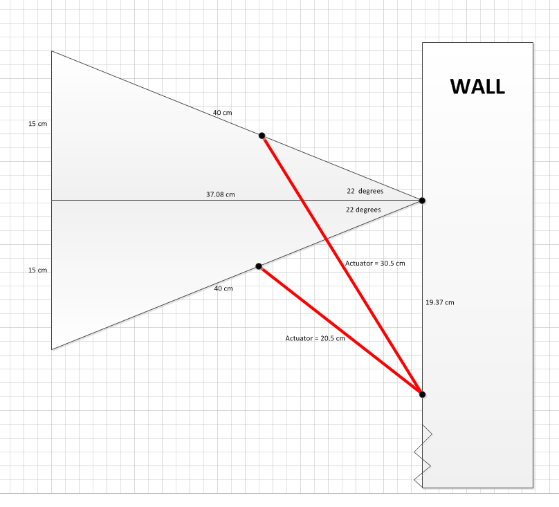
Now we are going to analyze the forces acting upon the arm. When choosing the dimensions of our arm, we did not exactly know where to start, so instead of calculating the optimal lengths via, for example, Matlab, we chose values we deemed realistic and sufficient. In retrospect the former seems like a more apt and reliable way to create the ideal arm and gripper. If we were to do this project again, we would certainly have done it differently. However, the way we did it does provide us with enough information to make all the calculations. The following information is required to analyze all the forces:
- The length of the arm: 40 cm
- The length of the large actuator retracted and fully extended: 20,5 and 30,5 cm
- We want to lift our arm to lift the cup 30 cm. This is to be sure we lift up the cup high enough.
- The point where the large actuator connects to the arm: at 3/7 the length of the arm (17,14 cm)
- The mass of the gripper holding a cup: we estimated this to be about 1 kg
Furthermore it’s important to know that we assume the following statements to be true:
- The arm has no mass
- The arm and gripper are rigid bodies
- All of the movement takes place in a 2D plane
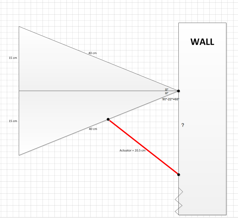
Firstly, it is important to create a full picture of our arm. To do that we have to calculate all the unknown sides and angles. Not only will this help us when making the graphical analysis, but it’s also vital to know this in order to construct our gripper properly.
The arm in the two extreme positions creates an isosceles triangle → We create two right-angled triangles which have two known sides: 15 cm and 40 cm long respectively →
arcsin(15/40)≈22,0°
So the angle between the arm with the actuator fully retracted and extended equals:
2*arcsin(15/40)≈44,0°
Now we consider the unknown distance between the joint connecting the arm to the wall and the joint connecting the (large) actuator to the wall. Let us look at the triangle formed by the actuator when retracted, the wall and a part of the arm. There are two known sides to this triangle and one known angle. The sides being 20,5 cm and (3/7)*40 ≈ 17,14 cm long. The angle is 90°-22° = 68°. Using the cosine rule we now calculate the distance between the joint connecting the arm to the wall and the joint connecting the (large) actuator to the wall:
(20,5)^2=(17,5)^2+x^2-2*17,14*x*cos(68°)
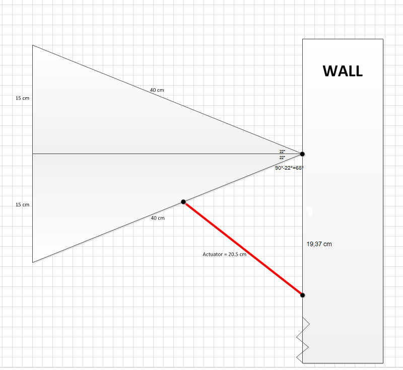
Solving this, we get:
x=19,37…cm
So the distance between the two joints, using our dimensions, is 19,4 cm.
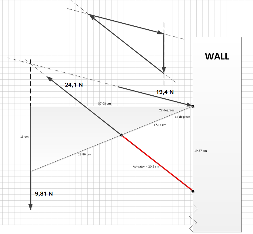
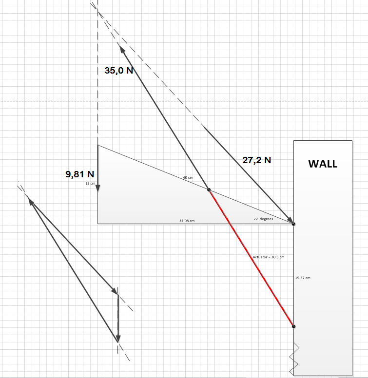
Now that all dimension of the arm are known, we can use a graphical analysis to know exactly how big the forces acting upon the arm are in both the extracted and retracted position: The only known force in both situations is the gravity pulling on the arm. It has a magnitude of 1,0*9,81=9,81 N. This force is represented by an arrow of an arbitrary length drawn downwards. We know the direction of the force produced by the actuator, since it is a two force member. The third force on the arm is the one acting upon the joint. Since all three forces have to traverse one point, we can also depict the direction of this force. Now, using a force triangle we can determine the size of the forces acting upon the arm, since all the forces are proportionally drawn. We determined the forces on the arm, when the actuator is retracted, to be (see drawing): 9,81 N 24,1 N 19,1 N We determined the forces on the arm, when the actuator is fully extended, to be (see drawing): 9,81 N 35,0 N 27,2 N
We can see that the forces that the actuator when retracted and extended has to deliver are 24,1 N and 35,0 N respectively. The actuator is able to deliver a force of about 44,0 N when extended (this was measured earlier for assignment 2), so our arm should be able to lift the cup.
Design & Process
Conditions
We started to design the frame based on the two most important conditions given:
- The ability to lift a cup with a mass up to 0.5 [kg]
- A minimum lifting distance of 0.25 [m] We made multiple possible designs and chose our final gripper through a series of morphological analyses (see this section below).
Solutions
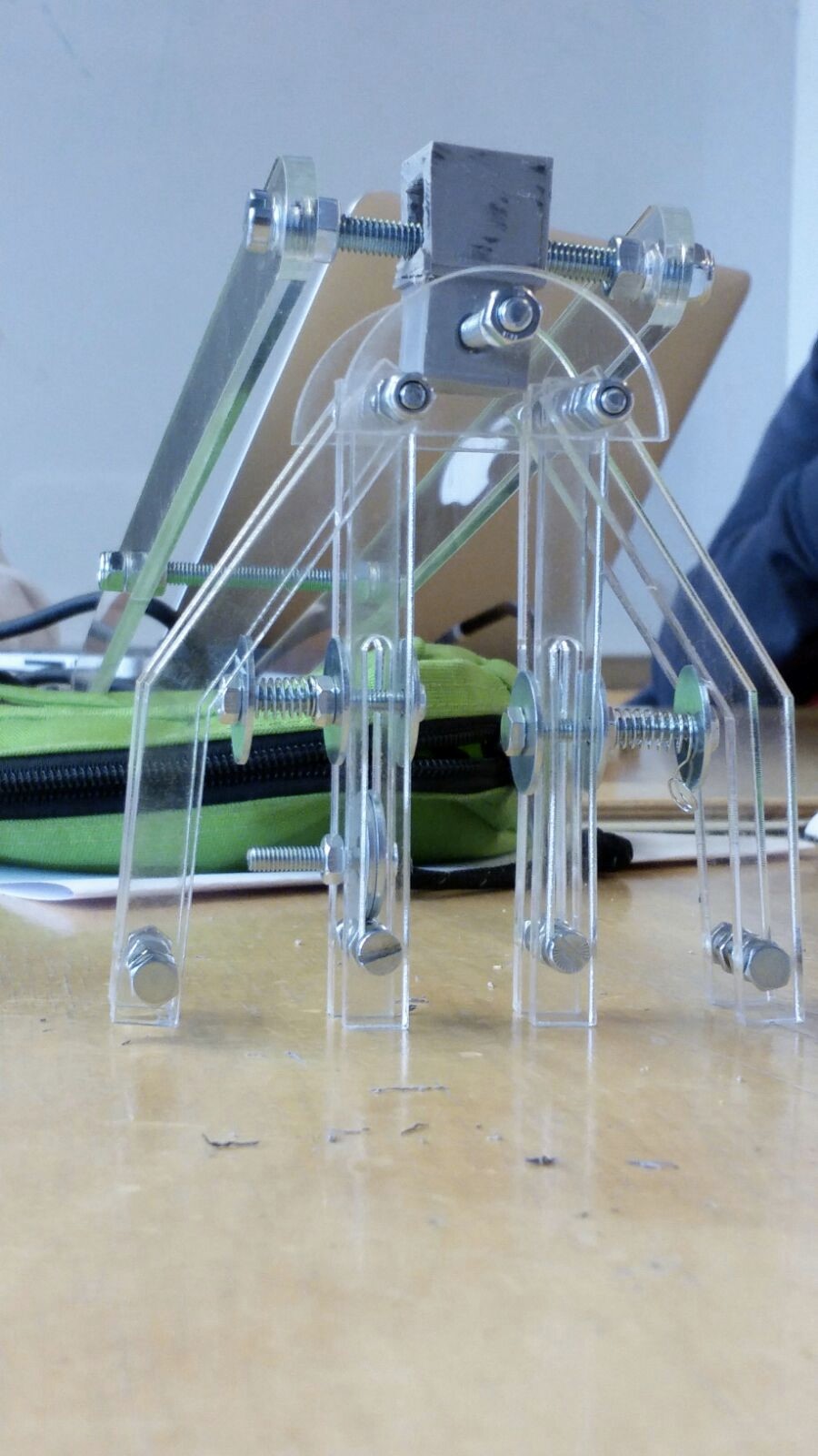
Having produced our design, we found that it was not possible to attach the actuator to the gripper. The original idea was to attach the end of the actuator to a bolt that would be able to slide through the slot (in the innermost fingers). However, connecting the end of the actuator to the bolt, or a nut on the bolt, turned out to be too unstable. We also did not have a way of connecting the other end of the actuator to the outermost fingers yet. We tried to tackle these problems in several ways, and due to a lack of time, this process mostly went by through trial and error. Multiple features were added and adjusted until we deemed it satisfactory.
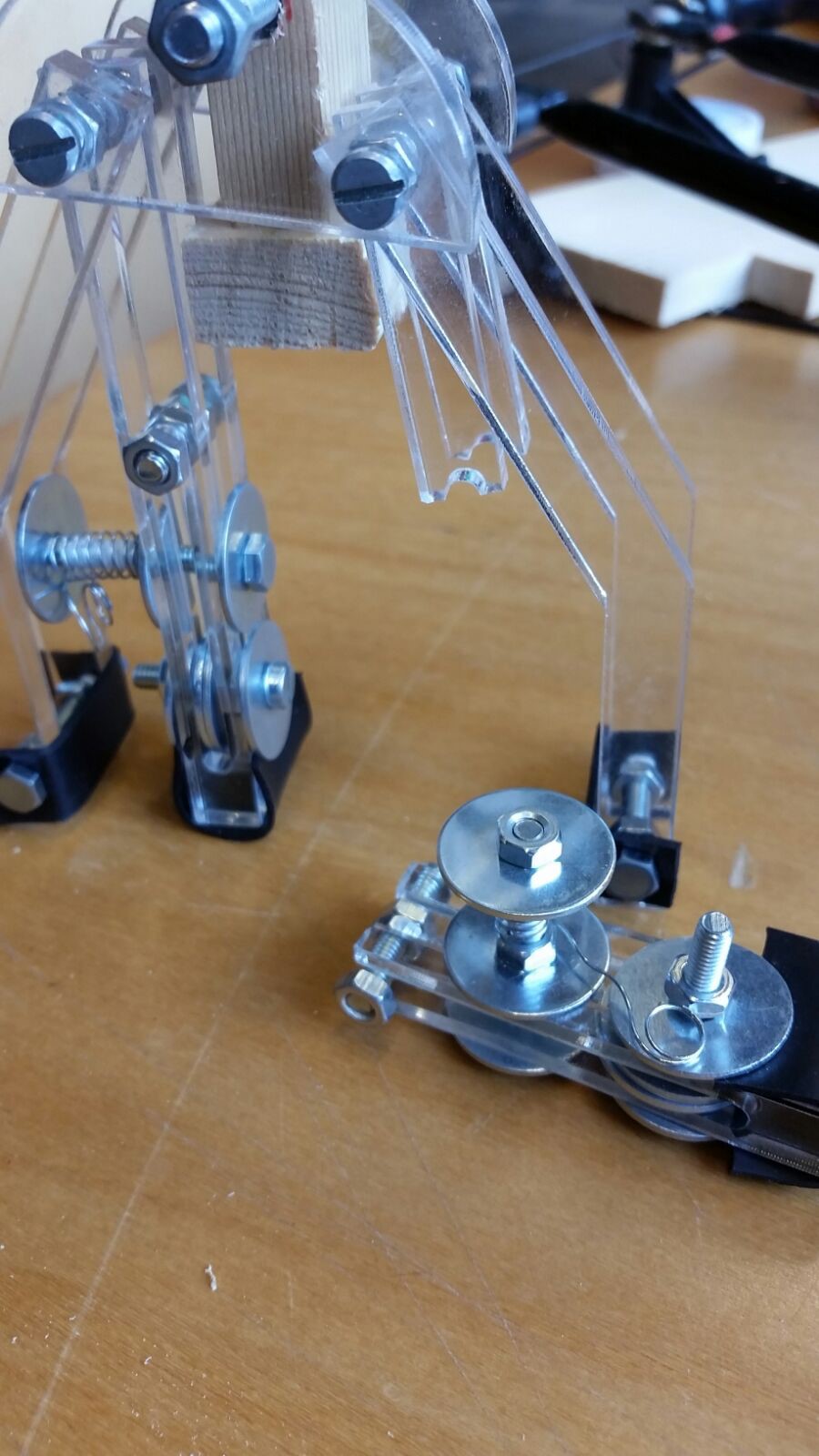
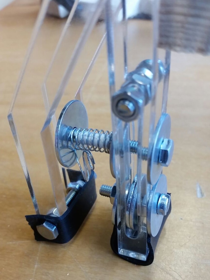
The actuators are now attached to the innermost fingers, by clamping two plain washers in each slot and attaching the actuators to the plain washers (see figure 1). When the actuators are at their full length, they rest on the bolts between each outermost finger. For these bolts we drilled extra holes in the perspex. In this position, without any correction, all four fingers would fall to the middle because of the actuator’s weight (2,4). To keep the innermost and outermost fingers at a certain distance from each other, we added the pressure springs. In this way, without any force, the inner and outer fingers stay seperated, but they can still be pushed together by the actuator’s pressure. These springs were not included in our original design. This pressure spring system is attached by a similar plain washer system as the actuator. To keep the two innermost fingers seperated, we designed a simple wooden piece connected to the transition piece between the arm and the gripper. This wooden piece keeps these two fingers at a constant distance from each other, corresponding to the approximate diameter of the cup (3).
To make sure the system has a better grip on the cup, we added a rubber strip on the end of each finger (4,5). The last day of the project, one of the perspex fingers broke off (6). The distance between the slot and the edge of the finger was too small and therefore this part was too weak. These fingerparts were adjusted in width and lasercut again. The outer fingers are solid (no slots), and therefore strong enough.
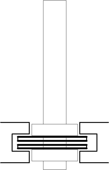
1. Figure 1
2. Attachment system for the actuators
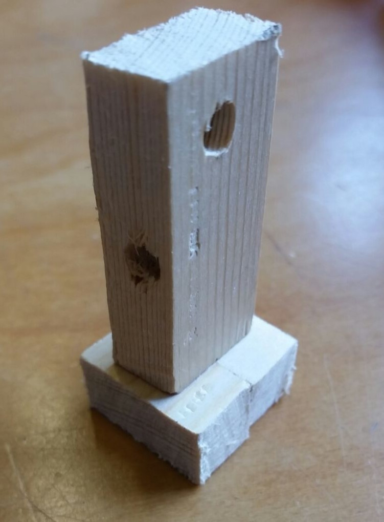
3. Wooden piece
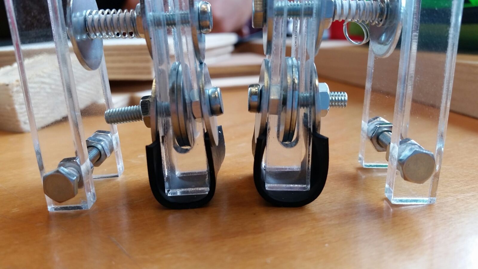
4. Rubber ends & actuator system
5. Rubber ends